Welcome to SkydioPilots.com
Sign up and join the discussion!
Sign up

Gimbal replacement wiring

dragand

New member
Joined
Dec 15, 2022
Messages
3
Reaction score
1
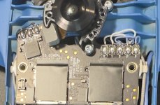
I am fixing a crashed S2 and have to replace the gimbal. The wires were cut and they are not marked. On the SD/Gimbal board, there are 2 pins marked Y (Yaw -- white wires), 3 pins marked P (Pitch -- blue wires) and 3 marked R (Roll -- black wires) and . The wires are not marked in any way, other than 2 are white and 3 each are blue and black. Does anyone have any clue how to correctly identify and solder the wires on the board?
 

Attachments

  • IMG_2669.jpg
    IMG_2669.jpg
    399 KB · Views: 5
PXL_20210626_010544047-4K.jpg


PXL_20210627_194902476-4K.jpg

These pics will zoom some. Let me know if you need more.
 
Last edited:
  • Like
Reactions: dragand
PXL_20210626_010544047-4K.jpg


PXL_20210627_194902476-4K.jpg

These pics will zoom some. Let me know if you need more.
Thank you! It turns out that the gimbal motors are non-sensored brushless, so the pinout for each motor is irrelevant (almost) if any motor starts acting up, just reverse any two wires to change the direction of rotation and it should work. I got the Roll and Yaw on the first try but the Pitch was reversed. Once I swapped the two wires, it started working OK.
 
  • Like
Reactions: Ridefreak

New Posts

Members online

No members online now.

Forum statistics

Threads
1,607
Messages
12,392
Members
2,372
Latest member
FRANCISCO MENDES MORAES